
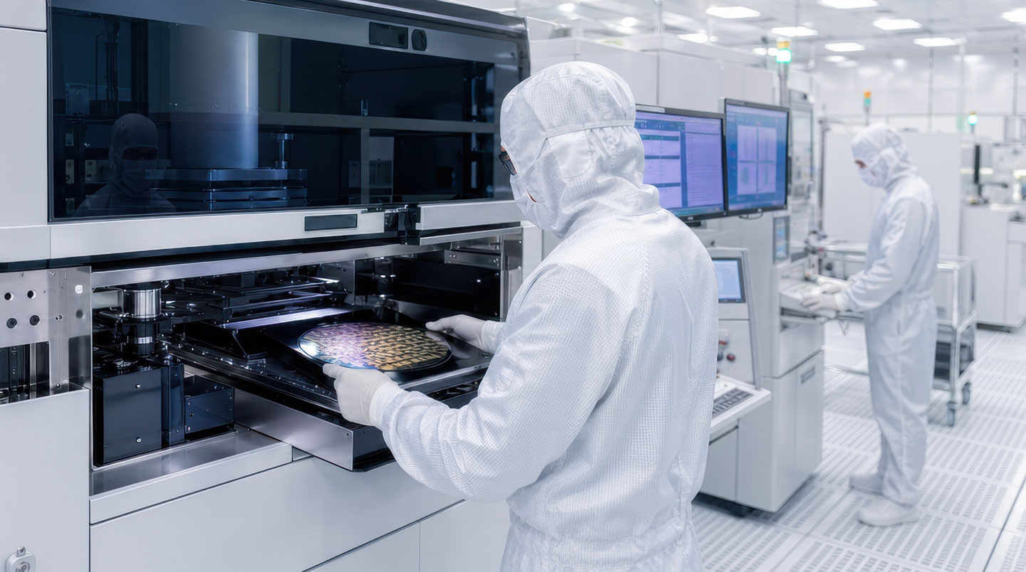
When a pre-aligner begins losing precision on your semiconductor production line, the diagnostic question isn’t whether to repair — it’s determining which failure mode is stealing your throughput. Research published in Micromachines (MDPI, 2023) confirms that pre-aligners serve as critical lithography gatekeepers, correcting wafer center and notch orientation before downstream processing. A misdiagnosis at this stage doesn’t just extend repair timelines — it compounds itself through every subsequent fabrication step while your equipment bleeds production capacity.
The financial stakes justify methodical diagnosis. According to 2026 consolidated data published by Relia Magazine, semiconductor fabs can lose millions of dollars per hour during unplanned downtime, with equipment failure accounting for 42% of all incidents across manufacturing industries. The pressure to restore production quickly often drives teams toward hasty repair decisions that address symptoms rather than root causes, creating a cycle of recurring failures that ultimately cost more than systematic initial diagnosis would have demanded.
Your Diagnostic Roadmap in 90 Seconds
- Pre-aligner failures trace to mechanical wear (approximately 60%), sensor drift (roughly 25%), or software issues (around 15%)
- Start diagnosis with symptom pattern: gradual precision loss indicates mechanical causes, erratic readings point to sensor failure, consistent offset suggests software alignment drift
- Validation testing requires 24-hour repeatability verification at ±0.05° tolerance; standard exchange programs (under 7 days) minimize downtime versus full refurbishment (3+ weeks)
Why Accurate Pre-aligner Diagnosis Determines Repair Success
Field diagnostics indicate that pre-aligner troubleshooting follows predictable failure mode distributions, yet maintenance teams frequently misidentify root causes by treating the first observable symptom rather than mapping symptom patterns to underlying mechanisms. The most common diagnostic error involves attempting software recalibration when bearing degradation is the actual culprit — an approach that temporarily masks symptoms without addressing the mechanical deterioration steadily contaminating your cleanroom environment.
Testing protocols reveal three dominant failure pathways, each producing distinct symptom signatures that enable rapid hypothesis formation. Mechanical bearing wear manifests as gradual precision degradation over weeks or months, typically with increased rotational resistance detectable during manual inspection. Encoder failures present differently — sudden accuracy loss with erratic position feedback creating inconsistent wafer placement your production monitoring flags immediately. Software alignment drift produces the most deceptive symptoms: consistent angular offsets that appear correctable through recalibration but don’t persist after parameter saves, often emerging after firmware updates or power disruptions.
Consider a 300mm fab experiencing intermittent wafer placement errors on one EFEM pre-aligner — roughly 3-5% of cycles show 0.2° rotational deviation, always in the same clockwise direction. Initial response: software recalibration, which temporarily masks symptoms for 48 hours before drift reappears. Systematic diagnosis following the framework below reveals consistent angular offset (pointing to software alignment), but parameter save verification discovers corrupted calibration file timestamps coinciding with a recent EFEM controller firmware update. Root cause: firmware update overwrote stored calibration coefficients. Resolution: calibration restoration from backup parameter file plus firmware rollback, restoring <0.05° precision within 4 hours versus the 2+ week encoder replacement originally planned based on initial symptom assessment. This scenario demonstrates how symptom pattern mapping prevents costly misdiagnosis.
The diagnostic framework below structures your investigation around observable symptom patterns, guiding you toward the statistically probable failure mode before investing hours in low-yield testing procedures. This decision tree approach mirrors how experienced reliability engineers mentally triage pre-aligner issues, eliminating unlikely failure modes through systematic symptom mapping rather than exhaustive component-by-component inspection.
-
If you observe: Gradual precision drift over weeks/months + increased rotational resistance
Hypothesis: MECHANICAL WEAR (bearing/encoder mechanism degradation). Validation test: Physical inspection for particulate contamination, manual rotation resistance assessment. Recommended action: Full mechanical refurbishment with bearing replacement and repeatability validation.
-
If you observe: Erratic position readings + sudden accuracy loss + inconsistent wafer placement
Hypothesis: SENSOR FAILURE (encoder optical disk contamination or electronic signal degradation). Validation test: Encoder voltage check, optical disk inspection, signal waveform analysis. Recommended action: Encoder assembly replacement with signal integrity validation.
-
If you observe: Consistent angular offset + post-firmware update issues + calibration doesn’t persist
Hypothesis: SOFTWARE ALIGNMENT DRIFT (parameter corruption or calibration data loss). Validation test: Parameter backup comparison, recalibration with save verification, firmware version audit. Recommended action: Calibration restoration with parameter backup implementation and firmware rollback if recent update correlates with failure onset.
Isolating the Root Cause: Testing Procedures for Each Failure Mode
Symptom-based hypothesis formation provides directional guidance, but confirmation requires targeted validation testing that either proves your initial assessment or redirects investigation toward combined failure scenarios. Industry experience demonstrates that roughly 20% of pre-aligner failures involve multiple simultaneous issues — commonly mechanical wear that generates debris contaminating encoder optical components, creating a hybrid failure profile that demands comprehensive refurbishment rather than targeted component replacement.
The systematic diagnostic approach begins with non-invasive observation before escalating to component-level testing. Document baseline symptoms with precision: measure and record the magnitude of positional drift (in degrees), note the frequency of placement errors (per hundred wafer cycles), capture error patterns your EFEM control system logs. This quantitative baseline becomes your validation metric after repair, confirming whether intervention restored equipment to specification or merely improved symptoms without achieving full recovery.
Visual inspection protocols yield substantial diagnostic information before you invest time in electronic testing. Bearing contamination appears as fine particulate residue around rotational assemblies — a telltale signature of friction wear that no amount of software recalibration will resolve. Cable integrity inspection catches the obvious failures: frayed insulation, connector corrosion, or physical damage from repeated flexing cycles. Encoder disk examination (requiring careful cleanroom protocols to avoid introducing new contamination) reveals whether optical pattern degradation or surface contamination is corrupting position feedback signals.
| Failure Type | Observable Symptoms | Diagnostic Test Protocol | Repair Timeline |
|---|---|---|---|
| Mechanical Wear | Gradual precision degradation, increased rotation resistance, particulate generation visible during inspection | Manual rotation resistance check, visual bearing inspection, precision drift trend analysis over multiple cycles | 3-8 weeks (full refurbishment) or under 7 days (standard exchange) |
| Sensor Failure | Erratic position feedback, sudden accuracy loss, intermittent communication errors logged by EFEM controller | Encoder voltage/signal check, optical disk contamination inspection, cable continuity verification | 2-4 weeks (encoder replacement) or under 7 days (standard exchange) |
| Software Alignment | Consistent angular offset, post-update issues, calibration parameter loss after power cycles | Parameter file comparison against backup, recalibration with save verification, firmware version audit | Hours to 2 days (on-site recalibration) if no underlying hardware damage |
Diagnostic validation becomes particularly critical when dealing with aging equipment operating beyond manufacturer-recommended service intervals. Pre-aligners approaching 50,000+ wafer cycle counts exhibit accelerated wear profiles where multiple failure modes converge — bearing degradation generates particulate contamination affecting encoder optical systems, creating hybrid failures requiring comprehensive analysis rather than component-targeted repairs.
When diagnostic complexity exceeds internal capabilities or demands specialized calibration equipment unavailable in typical maintenance departments, engaging OEM-certified service providers ensures systematic root cause identification. Professional diagnostic protocols include precision measurement tools, calibrated test fixtures, and comparative baseline data from known-good reference units — resources rarely available in-house that prevent misdiagnosis and unnecessary repair iterations.
-
Document baseline symptoms with precision metrics: drift magnitude in degrees, error frequency per hundred cycles, EFEM controller error log patterns
-
Conduct visual inspection: bearing contamination assessment, cable integrity check, encoder disk cleanliness verification following cleanroom protocols
-
Perform manual rotation resistance test: assess smoothness of motion, identify binding points, compare against baseline feel from known-good equipment
-
Execute encoder signal validation: voltage level verification, waveform quality analysis if oscilloscope available, signal consistency across rotation cycles
-
Review software parameter integrity: calibration timestamp verification, firmware version audit, parameter backup file comparison if available
Choosing the Right Repair Path: Standard Exchange vs Full Refurbishment
Diagnostic findings inform repair strategy decisions, but the optimal pathway balances technical requirements against business realities: downtime tolerance, budget constraints, and long-term equipment lifecycle planning. Published by the AEMT analysis on downtime economics reveals that the 500 largest companies globally lose approximately $1.4 trillion annually due to unplanned downtime — equivalent to 11% of total revenues — underscoring why rapid restoration often justifies premium service models over extended budget repair approaches.
Standard exchange programs deliver the fastest path to production restoration. Professional pre-aligner repair services offer certified solutions with guaranteed repeatability and minimal production impact, with specialized providers delivering OEM-quality refurbishment featuring full traceability and ISO9001-certified processes that ensure your equipment returns to production meeting original manufacturer specifications. The exchange model operates on a simple premise: you receive a fully tested, calibration-verified replacement unit (typically within 7 days) while your failed equipment undergoes comprehensive refurbishment for the provider’s exchange inventory pool. This approach eliminates the agonizing wait while repair work proceeds, immediately restoring your production capacity.
Full refurbishment represents the alternative pathway when exchange inventory availability doesn’t match your specific equipment model or when you’re managing planned downtime windows that accommodate longer repair timelines. Comprehensive reconditioning addresses all consumable components — bearings, encoder assemblies, drive mechanisms, calibration parameters — regardless of which single component triggered the initial failure. This preventive replacement strategy extends operational lifespan by resetting multiple wear mechanisms simultaneously, though it demands 3-8 week timelines depending on parts availability and the extent of required intervention. The trade-off calculation hinges on your downtime economics: if lost production during extended repair exceeds the premium cost of rapid exchange, the business case becomes straightforward.

Validation Requirements: Post-repair validation must include 24-hour continuous repeatability tolerance testing under wafer load, confirming ±0.05° precision specifications with certification documentation before production reintegration.

Common Questions About Pre-aligner Failure Diagnosis
How long does accurate pre-aligner diagnosis typically take?
Initial symptom-based hypothesis formation takes 30-60 minutes following systematic inspection protocols. Confirmation testing — encoder validation, calibration parameter verification, mechanical resistance assessment — requires an additional 2-4 hours. Comprehensive diagnosis including documentation typically completes within one shift, though complex combined failure modes may require extended observation of intermittent symptoms across multiple production cycles to establish pattern consistency.
What repeatability tolerance should you expect after repair?
OEM-specification repairs must restore equipment to original ±0.05° repeatability tolerance, validated through 24-hour continuous testing under wafer load conditions. Reputable service providers guarantee this specification with post-repair certification documentation including test data and traceability records. Tolerances exceeding ±0.1° after repair indicate incomplete restoration or use of inferior non-certified replacement components that won’t deliver production-grade precision.
Can you repair pre-aligners with multiple failures, and when does replacement make more sense?
Combined failures occur frequently, particularly when mechanical wear generates debris contaminating encoder optical components. Professional refurbishment addresses all failure modes simultaneously through comprehensive reconditioning, whereas targeted repairs risk leaving underlying issues unresolved. Replacement becomes economically justified when refurbishment exceeds 60-70% of new equipment price, obsolete models lack OEM-certified parts availability, or multiple previous repair cycles indicate systemic design limitations. For broader equipment lifecycle management considerations beyond immediate repair decisions, consult comprehensive equipment management frameworks addressing total cost of ownership analysis. For current-generation equipment, refurbishment typically delivers 40-60% cost savings versus replacement while maintaining production qualification.
How often should pre-aligners undergo preventive calibration?
Industry best practice recommends quarterly calibration verification for high-utilization equipment operating beyond 16 hours daily, with semi-annual checks sufficient for moderate-use installations. Precision monitoring systems enable predictive maintenance by flagging degradation trends before failures occur, shifting from time-based to condition-based intervention schedules. Environmental factors — cleanroom classification, temperature stability, vibration exposure — significantly influence optimal calibration intervals, with Class 1 cleanroom installations typically demonstrating extended calibration stability compared to less controlled environments.